The principle of a strain gauge force sensor
The operating principle of a strain gauge force sensor is shown in Figure 1. For simplicity, let us consider a steel rod of length and cross-section , subjected to a tensile force . The rod extends along its axis, and according to Hooke's Law, the extension is directly proportional to the applied force, i.e., .
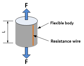
Assume that a resistive conductor with a cross-section is bonded along the entire length of the rod. Its electrical resistance is , where is the resistivity of the given conductor. As the rod extends, the length of the conductor increases while its cross-section simultaneously decreases. Consequently, the resistance of the conductor increases by a value . The relative resistance increase is also linear within a certain range and is ultimately directly proportional to the applied force. From this, the fundamental equation describing the conversion of a mechanical quantity (force) to an electrical one (resistance) can be derived:
The coefficient is called the k-factor (gauge factor). If we denote the relative strain as , then according to Hooke's Law for mechanical stress, applies, where is the modulus of elasticity of the rod. In practice, this means that the relative change in resistance will depend not only on the magnitude of the force but also on the properties of the material used. Therefore, it makes a difference whether the sensor is made of, for example, steel or aluminum. In practice, deformation is not measured using a simple resistive wire, but by a component called a strain gauge.
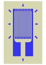
A common metal strain gauge is a foil measuring approximately 10 x 12 mm with a metal layer in the shape of a meander (Figure 2). The k-factor of a metal strain gauge is approximately 2. Semiconductor strain gauges also exist, which have a k-factor of up to approximately 200; however, they have other disadvantages, particularly thermal instability. Strain gauges are bonded to the body using a special epoxy-based adhesive. In practice, a single strain gauge is rarely used in sensor construction. Multiple strain gauges are applied to the body—most commonly four—and are connected in a bridge circuit. This results in a larger signal and better sensor characteristics. The nominal resistance of the bridge is typically 350 Ω.
Construction of a Simple Force Sensor
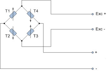
An example of a simple force sensor is a flat steel beam, cantilevered at one end and subjected to bending at the other (Figure 3). A total of four strain gauges are applied to the beam: two on the top and two on the bottom. When force is applied, the beam bends, causing the upper strain gauges (T1, T3) to stretch and the lower ones (T2, T4) to compress. To maximize the signal, the strain gauges are connected in a bridge circuit as shown in Figure 4. Strain gauges T1 and T3 increase their resistance, while T2 and T4 decrease theirs.
If a supply voltage is connected to the bridge between the Exc+ and Exc- terminals, the voltage across the bridge diagonal will increase (relative to the + and - terminal markings). Most standard strain gauge force sensors operate on this principle—where one part of the sensor structure compresses and another part stretches under force. The structural body is called the deformation element, and four strain gauges (two compressing, two stretching) are typically applied to it and connected in a bridge.

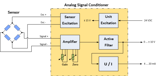
Connecting the Sensor to an Electronic Unit
Based on the construction of the strain gauge force sensor, it is clear that the electronic signal processing unit must consist of at least two parts: a supply voltage source for the bridge and a signal amplifier. Such a unit is commonly called a transmitter (or signal conditioner), and its block diagram, including the sensor connection, is shown in Figure 5. As can be seen, the transmitter includes several other blocks. A transmitter power supply block is necessary when a negative voltage is also required at the output. An active filter is used to reduce noise and increase the stability of the output signal. For some transmitters, the filter's cutoff frequency can be switched. A current converter is essential if a current signal output is required. All these blocks are featured in the EMS169 and EMS170 transmitters.