Guide to Strain Gauge Sensor Parameters: How to Select and Calculate Accuracy?
Strain gauge force sensors are the heart of industrial weighing and force measurement. However, to achieve accurate results, it is not enough to know only the maximum capacity. In this article, we will break down the key technical parameters that influence sensor behavior in real-world conditions.
1. Measuring Range and Safe Load Limit
When designing an application, it is important to consider not only the absolute magnitude of the force but also its nature.
- Nominal Range (Fn): The force for which the sensor was designed and at which the specified parameters apply. It is given in units of force, or weight if the sensor is intended for weighing.
- Service Range: The force applied to the sensor at which no permanent damage occurs. It is expressed as a % of the nominal range, with typical values being 120 – 150 % Fn.
Practical Advice: When designing the sensor range, other characteristics of the loading force are also important, not just its absolute magnitude. In applications where the sensor is permanently loaded, we recommend not exceeding 75 % Fn, and for dynamic loading (vibrations, shocks), we recommend not exceeding 50 % Fn.
2. Sensitivity and Supply Voltage
- Nominal Sensitivity (Cn, Cnom) characterizes the magnitude of the output signal and is given in units of
mV/V (millivolts per volt). Common sensitivity values range from 0.5 to 3 mV/V.
Output signal calculation:
For example, with a sensitivity of 2 mV/V and a 10 V supply, we get 20 mV at the output.
- Sensitivity Tolerance is the deviation of the actual sensitivity from the nominal value. It is expressed in % of the nominal sensitivity, and a common value is ± 2 % Cn.
- Zero Balance (Zero Tolerance) is the signal at the sensor's output at zero applied force. It has the same physical unit as
sensitivity (mV/V) but is usually expressed in % of the nominal range.
Example: If the zero tolerance is e.g. ± 2 % Cn and the nominal sensitivity is 2 mV/V, the output of the unloaded sensor is as follows:
With a supply voltage of 10 V, this represents an output voltage of:
- Nominal Supply Voltage of the sensor is the voltage value at which its parameters were measured. The voltage can be DC or AC, and standard values typically range from 2.5 V to 15 V.
- Supply Voltage Range is the safe value of supply voltage at which there is no risk of performance degradation or damage to the sensor. The upper limit can be especially critical. Exceeding it may cause sensor self-heating and, consequently, an increase in thermal error.
3. Input and Output Resistance
- Input Resistance is the sensor's resistance in Ω measured between the power supply terminals.
- Output Resistance is the sensor's resistance in Ω measured between the signal terminals.
4. Temperature Range and Thermal Errors
- Nominal Temperature Range is the temperature range within which the sensor was tested. It is sometimes called the compensated temperature range because the thermal error is measured and compensated within this range.
- Operating Temperature Range is usually wider than the nominal range. The sensor can be used in this range without issues; however, since it was not tested in this range, the thermal error may be larger than stated in the datasheet.
- Temperature Coefficient of Zero (TKo) indicates how the output signal of an unloaded sensor changes with temperature. It is given in % of nominal sensitivity, and a common value is ± 0.1 % Cn / 10 °C.
- Temperature Coefficient of Sensitivity (TKc) indicates how the sensor's sensitivity changes with temperature. It is given in % of nominal sensitivity, and its value is approximately ± 0.1 % Cn / 10 °C.
5. Linearity and Hysteresis Error
These errors define the accuracy of the transfer characteristic relative to an ideal state.
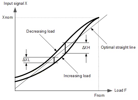
- Linearity Error (Non-linearity) is the maximum deviation of the sensor's transfer characteristic during increasing
load from the optimal straight line. It is given in % of the nominal range. The definition does not specify the method for determining the
optimal straight line. Several methods exist, but in practice, the least squares method is sufficient. The calculation is based on at least 5 points of the measured transfer characteristic. Non-linearity is calculated according to the formula:
- Hysteresis Error (Hysteresis) is the maximum deviation between the sensor's characteristics during increasing
and decreasing load, relative to the nominal range. It is calculated according to the formula:
6. Using Parameters for Error Calculation
For calculations, let's assume we have a sensor with the following parameters:
- Fn = 1000 N
- Cn = 2 mV/V
- TKo = 0.1 % Cn / 10°C
- TKc = 0.15 % Cn / 10 °C
- Linearity error NL = 0.2 % Fn
- Hysteresis error H = 0.25 % Fn
- Ambient temperature changes within the range ΔT = 30 °C
With a temperature change of ΔT = 30 °C, the output signal changes by:
Similar to the previous case, we first calculate the change in the output signal with a temperature change of ΔT = 30 °C:
The linearity error is 0.2 % of the nominal range Fn:
The hysteresis error is 0.25 % of the nominal range Fn:
We consider errors to be random variables, and the above calculations (or estimates) of errors can be (with some simplification) considered as Type B uncertainties. Then the total error is calculated using the root sum square method of partial uncertainties, i.e., according to the formula: